
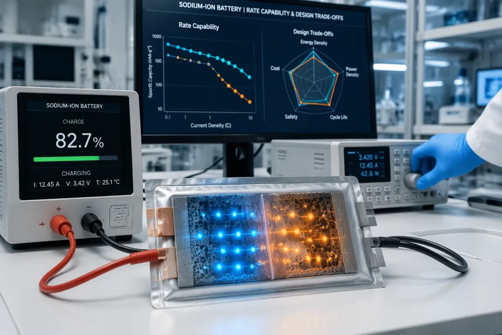
Can a sodium-ion cell charge quickly without giving up energy density, cycle life, safety or cost? That question is at the heart of every Fast-Charging Sodium-Ion design decision. The kinetic bottlenecks set the limits. Hard carbon pore-filling is the most demanding, because sodium storage inside pores controls how fast the anode takes in charge. Material choices, electrolyte chemistry, charging protocols and thermal control each offer a way forward. Each route also comes with a compromise. Engineers and industry professionals need a clear view of where fast-charging sodium-ion fits and which design levers are still available. This discussion frames those trade-offs directly.
Key Takeaways
Fast charging a sodium-ion cell means balancing speed against energy density, cycle life, safety and cost.
Hard carbon anodes slow down charging, because sodium ions have to travel deep into the pores. Smaller particles help with this.
Electrolyte design and charging methods protect the anode and make fast charging work better.
Different uses need different designs: short charging times work well for fleets and two-wheelers, while long-range storage needs slower charging.
Every design choice involves trade-offs, so engineers should first map out the duty cycle to choose the right compromise.
Fast-Charging Sodium-Ion Targets and Demand
Defining Rate Capability Goals
Industry benchmarks give engineers a shared reference point for rate capability. A widely cited target sets 80% state of charge in 15 minutes. Full charging within 0.1 hours is a more demanding goal. Discharge durations up to 1 hour define the companion requirement for high-power duty. These figures act as design targets rather than performance guarantees. A cell that meets the 15-minute benchmark in the lab may fall short in a pack with real thermal constraints.
Quantitative comparisons suggest an advantage for sodium chemistry on the anode side. Hard carbon anodes can reach faster charging rates than lithium-ion counterparts in like-for-like measurements. This headroom matters for applications that prioritise short recharge windows. The advantage does not carry over automatically to full-cell performance. Cathode kinetics, electrolyte transport and cell design still govern the achievable rate.
Applications Driving Fast Charging
Several application classes push fast-charging sodium-ion development forward. Electric two- and three-wheelers need short turnaround times at depots and swap stations. Urban delivery fleets face tight duty cycles with brief windows for opportunity charging. Grid buffer and frequency-regulation systems demand high-power pulses rather than deep energy draws. Portable power tools and small mobility devices value rapid top-ups between tasks.
Each application weights the targets differently. A fleet vehicle may accept a 15-minute partial charge and tolerate a longer full charge overnight. A grid buffer may never reach full charge at all. Engineers should therefore map the benchmark to the duty cycle rather than treat it as a universal specification. The next sections examine where the kinetic limits actually sit.
Hard Carbon Kinetics
Sodium Storage and Diffusion Limits
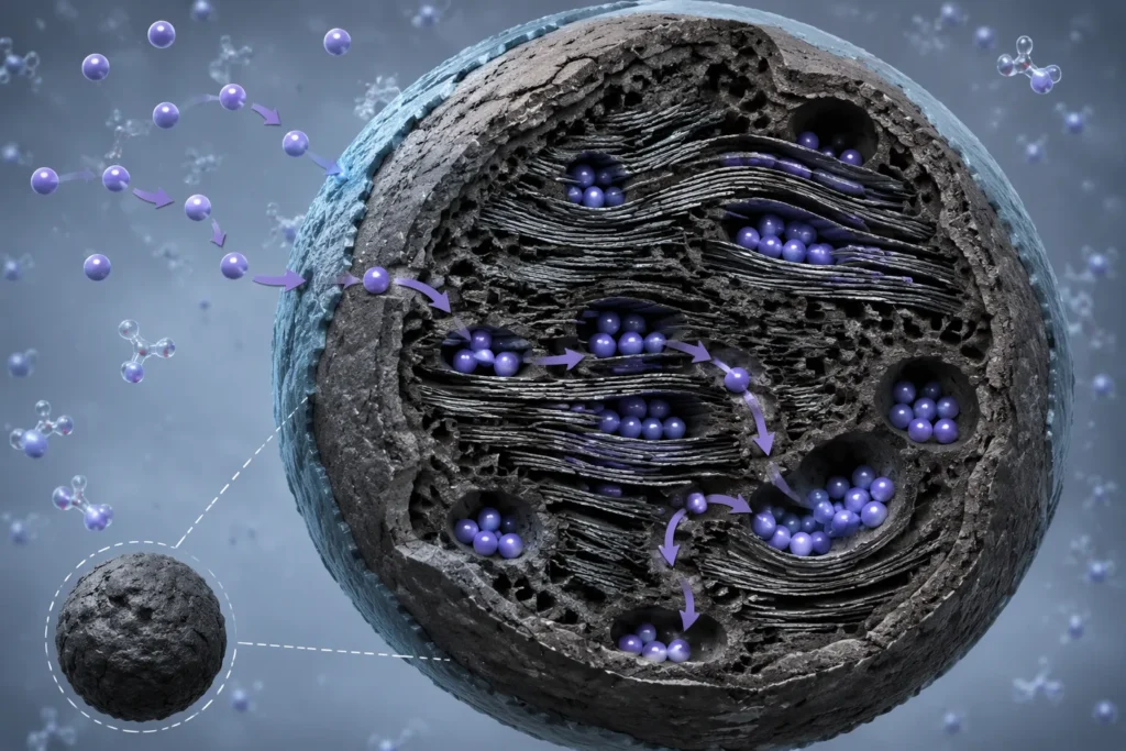
Hard carbon holds sodium in a few different ways. Sodium ions stick to defect sites and graphene surfaces. They also slip between the messy carbon layers. A third route fills closed pores inside the carbon framework. Each route has its own speed penalty.
Diffusion limits show up at every scale. Ions must travel through the electrolyte, cross the solid electrolyte interphase, and then move inside the carbon particle. Solid-state diffusion inside the particle is often the slowest step. A big particle makes the diffusion path longer. The diffusion time goes up with the square of that path length. This link explains why particle size matters so much for rate capability.
The diffusion pathway follows a clear order:
Ion transport through the bulk electrolyte.
Desolvation and interphase crossing at the particle surface.
Migration through the disordered carbon matrix.
Final storage at defects, between layers, or inside pores.
Any step that fills up early caps the whole cell. Engineers therefore measure each step on its own before picking a design lever.
Pore-Filling Kinetics and Trade-Offs
Faster pore-filling kinetics is a key need for better hard carbon in fast-chargeable sodium-ion batteries. Pore filling gives a large share of reversible capacity at low voltage. The process depends on sodium ions reaching deep pore sites and plating there in a quasi-metallic state. Narrow pore entrances slow this access. Long diffusion distances inside the particle slow it even more.
Hard carbon composition and structure directly shape fast-charging capability. A high closed-pore volume raises capacity. It also makes the ion path longer and can trap sodium during rapid charge. A higher pyrolysis temperature usually makes closed pores bigger and improves storage. The same treatment can cut surface defects and lower rate performance at the surface. The precursor choice sets the baseline pore architecture. Biomass precursors offer porosity you can tune. Polymer precursors offer tighter structural control.
These choices bring real trade-offs. A structure tuned for fast pore filling often stores less total sodium, which lowers energy density. Heavy pore engineering can also weaken the carbon framework. Mechanical stress builds up during repeated rapid cycling. Cracks then expose fresh surfaces, and fresh surfaces use up electrolyte. Cycle life drops as a result.
Engineers face a three-way balance. Rate capability pulls toward thin walls, short diffusion paths and open porosity. Energy density pulls toward high closed-pore volume. Cycle life pulls toward a strong, stable framework. No single hard carbon structure is best on all three. The right compromise depends on the duty cycle. A power-focused Fast-Charging Sodium-Ion design takes lower capacity for speed. An energy-focused design takes slower charging for range.
Material Design for Rate Capability
Anode Architectures and Doping
The way the anode is built sets how far sodium ions must travel. Smaller particles mean a shorter path through the solid material. Porous or hollow shapes add surface area and bring storage sites closer. Both ideas boost rate capability. Both also lower packing density and volumetric energy density. Engineers must therefore match particle size to the target charge time.
Doping changes the carbon framework itself. Nitrogen doping adds defects that improve electronic conductivity and sodium adsorption. Phosphorus doping widens the spacing between layers and makes ion movement easier. Boron doping can keep the pore structure stable during cycling. Each dopant shifts the balance between speed and capacity. ⚡ Rate gain versus energy loss is the main trade-off here.
Reviews of anode materials for fast-charging solid-state sodium batteries point to the key factors that control rate capability. These factors include bulk diffusion, interfacial resistance and electronic percolation. The same principles apply to liquid-electrolyte cells. A Fast-Charging Sodium-Ion design therefore gains from anode work that tackles all three factors together.
Cathode and Electrode Engineering
Cathode kinetics often hold back the full cell. Layered oxides and Prussian blue analogues offer different transport behaviour. Particle morphology, coating and carbon additive distribution all affect rate. Thin electrodes shorten the ion path in the electrolyte. They also reduce areal loading and energy density per unit area.
Electrode engineering must balance electronic and ionic pathways. A well-designed conductive network supports high current. Too much additive pushes out active material. Designers should treat electrode thickness, porosity and additive fraction as linked variables. Each choice moves the cell along the rate-versus-energy curve.
Coating active particles with a conductive layer can lower interfacial resistance. The coating adds cost and process steps. It also adds mass with no capacity. ⚖️ Engineers should weigh the rate benefit against the added cost for each application.
[Figure: schematic of anode architectures and doping strategies — placeholder]
Electrolyte and Interphase Design
Salt and Solvent Selection
The electrolyte moves sodium ions between the electrodes. The choice of salt and solvent sets how fast the ions travel. Fast charging needs high conductivity and low viscosity. A poorly chosen solvent slows ion movement and makes the cell more resistant.
Salt selection brings its own balance. Common sodium salts give good conductivity at a moderate cost. Other salts can widen the electrochemical window and improve thermal stability. They often cost more and need careful handling. Solvent blends follow a similar pattern. Low-viscosity solvents speed up ion transport. High-boiling solvents improve safety and high-temperature behaviour. Designers should match the blend to the duty cycle rather than chase one best formula.
Interphase Stability at High Rates
The solid electrolyte interphase forms on the anode surface during the first cycles. This thin layer protects the electrolyte from further breakdown. Fast charging puts the interphase under heavy stress. Rapid volume changes and local heating can crack the layer. Fresh anode surface then meets the electrolyte, and new interphase grows. This cycle uses up electrolyte non-stop and causes steady capacity fade.
[Figure: schematic of the solid electrolyte interphase and its stability at high rates — placeholder]
Electrolyte strategies each carry trade-offs between ionic transport, interphase stability and cost:
🔋 Additive blends form a tougher, more elastic interphase. They add cost and can lower conductivity.
⚡ High-concentration salts steady the interphase at high current. They raise viscosity and cost.
🧪 Co-solvent systems improve low-temperature transport. They may weaken long-term interphase stability.
A Fast-Charging Sodium-Ion cell needs an electrolyte tuned for both speed and layer durability. No single formulation wins on all three fronts. Engineers should test candidate electrolytes under the target charge profile, not only in slow-rate cycling.
Charging Protocols and Cell Balancing
Multi-Stage and Pulse Charging
A single fixed current setting rarely works well for a fast-charging sodium-ion battery. The cell takes high current easily when it is nearly empty but resists it near full charge. A multi-stage protocol adjusts to this pattern. The charger sends a strong steady current first, then lowers it as voltage climbs, and ends with a constant-voltage hold. Each step keeps the interphase from getting too much stress.
Pulse charging gives a second option. The charger sends short bursts of current and puts brief rests between them. These rests let sodium spread out inside the hard carbon pores and stop local depletion. A typical sequence goes like this:
Pre-charge at low current to wake the cell safely.
High-current boost up to a mid state-of-charge threshold.
Stepped taper with short rest pulses.
Constant-voltage finish with a cut-off criterion.
Protocol Trade-Offs in Cycle Life
Every protocol choice moves stress to another place. ⚡ Aggressive boost stages cut charge time and raise heat generation. 🔋 Gentle taper stages protect cycle life and make the session longer. ⚖️ Pulse rests ease pore filling and make charger hardware more complex.
Cell balancing belongs in the same discussion. Weak cells hit the upper voltage limit first during fast charge. A passive balancer drains energy and wastes heat. An active balancer moves charge between cells and adds cost and complexity. Engineers should match the balancing strategy to the protocol, because a fast profile makes any cell-to-cell mismatch worse.
Industry Approaches and Patents
Comparing Commercial Strategies
Cell makers and material suppliers take several different paths for fast-charging sodium-ion batteries. Each path targets a different bottleneck, and each one suits a different product class.
One group focuses on hard carbon pore engineering. These teams adjust precursor choice and pyrolysis conditions to make sodium diffusion paths shorter. The approach suits power-focused products such as two-wheelers and grid buffers. It gives up some energy density for speed.
A second group patents electrolyte formulations. Additive packages and co-solvent blends aim to keep the solid electrolyte interphase together under high current. This route suits cells that must combine fast charging with long cycle life, such as fleet delivery vehicles.
A third group protects charging protocols and balancing architectures. Multi-stage profiles and active balancing circuits reduce stress on weak cells. These patents suit pack integrators more than cell manufacturers.
A fourth group works on solid-state anodes. Reviews of anode materials for fast-charging solid-state sodium batteries set out the governing factors, and patent filings follow that science. This route is still at an earlier stage of commercial maturity.
Strategy family | Primary lever | Best fit |
|---|---|---|
Pore-engineered hard carbon | Anode structure | Power tools, grid buffers |
Electrolyte additives | Interphase durability | Fleet and long-life cells |
Protocol and balancing patents | Pack control | System integrators |
Solid-state anodes | Interfacial resistance | Emerging high-energy designs |
Patent Landscape and Implementation
The fast-charging sodium-ion battery patent landscape spreads across these four families. Applicants can search granted families and pending applications through Espacenet and WIPO PATENTSCOPE. Google Patents offers full-text searching across jurisdictions.
Implementation depends on freedom to operate. A cell maker that licenses pore-engineering claims still needs its own electrolyte and protocol position. Broader market context appears in reports from the IEA and IRENA. No single family dominates, and each fits a defined role.
Safety and Thermal Management
Heat Generation at High Rates
Sodium-ion cells make much more heat when they charge fast. Resistance in the cell, the interphase layer and pore-filling losses all turn electrical energy into heat. Thermal imaging of a pouch cell on a fast profile usually shows a hot band near the tabs. It also shows a warmer core than the edges. A heat map like this helps engineers spot current crowding before it causes a failure in the field. Uneven temperature across the stack speeds up local ageing and makes cell-to-cell mismatch worse.
⚠️ A cell that runs hot during fast charging loses capacity faster and has a higher risk of thermal runaway. Engineers should measure heat generation under the target charge profile, not only at slow rates.
Balancing Safety Against Speed
Thermal management for fast-charging sodium-ion cells involves a direct compromise. Aggressive cooling adds mass, volume and cost, and it uses energy. Modest cooling keeps the pack light and cheap, but it leaves less margin during repeated fast sessions. 🔥 Designers should size the cooling path to the worst-case duty cycle rather than the average one.
Cell chemistry choices shift this balance too. A hard carbon tuned for rapid pore filling may run cooler at high current, but it stores less energy. A denser electrode charges more slowly and spreads heat more evenly. ⚡ Safety, speed and cost therefore move together, and no single setting optimises all three.
Fast-Charging Sodium-Ion Design Trade-Offs
Mapping the Compromises
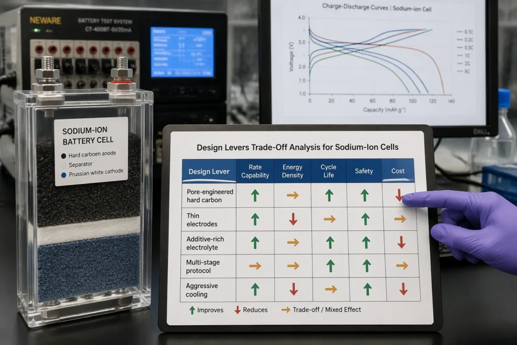
Every design choice moves the cell on several fronts at the same time. Material choices set the base for how ions move and how much energy is stored. Electrolyte chemistry controls ion movement and how long the interphase lasts. Protocol design shapes how stress builds up over time. Thermal management decides how much stress the cell can take. A change in one area seldom leaves the others alone. An anode built for speed makes the electrolyte work harder. A protocol that cuts charge time pushes heat into the cooling system. Engineers who treat these choices as separate pay for that mistake later in cycle life or cost.
The table below maps the main choices against five performance features. Each arrow shows which way things move when engineers push that choice toward faster charging.
Design lever | Rate capability | Energy density | Cycle life | Safety | Cost |
|---|---|---|---|---|---|
Pore-engineered hard carbon | ⬆️ Higher | ⬇️ Lower | ⚖️ Mixed | ⚖️ Mixed | ⬆️ Higher |
Nitrogen or phosphorus doping | ⬆️ Higher | ⬇️ Lower | ⚖️ Mixed | ➡️ Neutral | ⬆️ Higher |
Thin electrodes | ⬆️ Higher | ⬇️ Lower | ⬆️ Higher | ⬆️ Higher | ⬆️ Higher |
Additive-rich electrolyte | ⬆️ Higher | ➡️ Neutral | ⬆️ Higher | ⬆️ Higher | ⬇️ Higher cost |
Multi-stage protocol | ⬆️ Higher | ➡️ Neutral | ⬆️ Higher | ⬆️ Higher | ➡️ Neutral |
Aggressive cooling | ⬆️ Higher | ⬇️ Lower | ⬆️ Higher | ⬆️ Higher | ⬇️ Higher cost |
Fast charging raises electrochemical stress on every part inside the cell. Each part sees sharper swings in sodium concentration and temperature. Hard carbon needs special attention. Its pore-filling step is sensitive to current density and local depletion. A protocol tuned on a graphite-like assumption will overstress a pore-rich carbon. Engineers should therefore develop charging protocols alongside the hard carbon specification, not after it. The pore structure and the current profile form one design problem. A carbon with wide pore entrances handles a stronger boost stage. A carbon with narrow entrances needs longer rest pulses and a gentler taper.
Cost deserves a separate mention. Every choice that raises rate capability adds process steps, materials or system hardware. Pore engineering, doping, additives, active balancing and cooling each add cost. The penalty adds up across the pack, not just the cell.
Fit by Application
No single setup serves every duty cycle. The right compromise follows from what the application values most. A depot-charged delivery fleet cares about cycle life and interphase durability. Electrolyte additives and gentle taper stages fit this class well. A two- or three-wheeler cares about recharge windows. Pore-engineered hard carbon and a strong boost stage suit that duty. A grid buffer rarely reaches full charge. Thin electrodes and modest cooling keep the pack responsive without paying for energy it never stores. A long-range storage installation values energy density. Denser electrodes and slower profiles accept longer charge times in exchange for more stored energy.
🚚 Depot-charged fleets: cycle life and interphase durability come first. Additive electrolytes and taper stages fit best.
🛵 Two- and three-wheelers: short recharge windows come first. Pore-engineered carbon and boost stages fit best.
⚡ Grid buffers: pulse power comes first. Thin electrodes and modest cooling fit best.
🔋 Long-range storage: energy density comes first. Denser electrodes and slower profiles fit best.
Each row in the table stands for a real engineering choice with a cost you can measure. Teams that map their duty cycle first avoid paying for rate capability they will never use. They also avoid under-specifying the anode and finding the shortfall during field charging. A Fast-Charging Sodium-Ion design review should weight the five features from the duty cycle and score candidate setups against that weighting.
The trade-off map stays the same across the whole design space. Rate capability competes with energy density, cycle life, safety and cost. Material choices set the starting point. Electrolyte chemistry controls how long the interphase lasts. Protocol design shapes stress over time. Thermal management decides how much stress the cell can take. Each lever moves several features at once, so no setting wins everywhere.
In business terms, fast-charging sodium-ion fits best where short recharge windows matter more than maximum range. Depot fleets, two- and three-wheelers and grid buffers lead that list. Long-range storage still favours denser designs that charge more slowly. Future gains will likely come from pairing pore-engineered carbon with matched protocols. They will also come from electrolytes that hold the interphase together at high current. These directions ease today’s compromises without removing them.
FAQ
What limits the charging speed of a sodium-ion cell?
A few steps set the limit. Ions must cross the electrolyte, pass the solid electrolyte interphase and diffuse through the carbon particle. Solid-state diffusion inside the particle is often the slowest step. Particle size matters a lot, because diffusion time rises with the square of the path length.
Why does hard carbon pore-filling slow fast charging?
Pore filling stores a large share of capacity at low voltage. Sodium ions must reach deep pore sites through narrow entrances. Long diffusion paths inside the particle add more delay. A structure tuned for rapid pore filling usually stores less total sodium, so energy density falls.
Which electrolyte properties matter most at high current?
High ionic conductivity and low viscosity help ions move quickly. A stable interphase matters just as much. Fast volume changes can crack the layer, and fresh surface then uses up electrolyte. Additive blends and high-concentration salts each help, yet both add cost and can lower conductivity.
How does a multi-stage protocol protect the anode?
A multi-stage profile sends strong current while the cell is nearly empty. It then tapers the current as voltage climbs. Short rest pulses let sodium spread inside the pores. This sequence limits local depletion and eases stress on the interphase. A Fast-Charging Sodium-Ion pack therefore pairs the protocol with matched cell balancing.
Where does fast charging fit best commercially?
Short recharge windows matter most for depot fleets, two- and three-wheelers and grid buffers. Long-range storage still favours denser electrodes and slower profiles. Each duty cycle weights rate capability, energy density, cycle life, safety and cost differently, so engineers should map the application first.